Sorts of Flex Rigid Circuit Boards use In PCB

The PCB board is generally used in electronics as a base material which is often made up of composite epoxy, fiberglass or any composite materials. As you understand that they are primarily associated with computer systems, various kinds of those boards are utilized in different fields additionally, depending upon the requirement. These are made up of fabric which will be flexible as well as movable. If you have any kind of concerns pertaining to where and ways to utilize printed circuit board cost, you can contact us at the website. The Flex-rigid circuit board prices are usually higher due to the fabrication process. It has extra advantages over the rigid ones. They can be wrapped round corners. The weight also decreases since it is a single-layered board. It is utilized in materials which wants waterproofing, corrosion-resistant and shock proofing. They’re particularly designed to transmit indicators which are a couple of gigahertz. The Flex-inflexible circuit boards made up of high-frequency boards which include polyphenylene oxide (PPO) resin, glass-reinforced epoxy laminate, and Teflon. If a board is made up of a single layer of fabric it is known as single-layered boards.

Only one aspect of the board is made up of steel. As you recognize that copper is an electrical conductor, so it’s used within the coating. After the coating with the copper is done, then a protective mask is applied and above that silkscreen. They have their varied components and circuit placed on one facet only. These boards are easy to design and the manufacturing price can be fairly low if made in excessive volumes. When the board is made up of a thin layer of material corresponding to copper on each sides of the boards is known as double layered boards. The circuit on one facet of the board connects the opposite facet of the board by drilling holes. They are often connected in one other approach additionally which is through surface mounting. In this methodology, fairly much less area is used as small leads are directly soldered into the board. This enables the board to supply extra functions by growing the pace and also decreases the load. This is made up of a cloth that prevents the board from twisting. A pc motherboard is the most effective instance of the inflexible boards. It’s designed to allocate electricity and permitting them to speak between the various components of the computer. They comprise the most important share in the PCB markets. These inflexible boards could be anything from a single-layered to seven to eight layered multi-layered inflexible boards. Instead of using fiberglass they are made up of copper or aluminum boards. They are surroundings-pleasant and are inexpensive. They can be simply recycled and is also a better method to converse energy. Aluminum boards are much more durable in comparison with different supplies that reduce the injury that’s induced throughout installation and shipping.

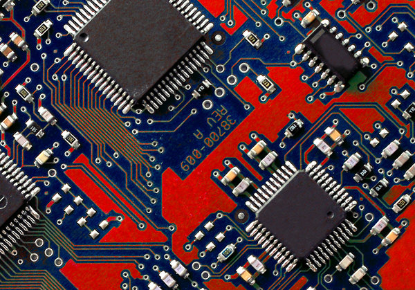
The world is rising at a very fast pace in terms of fashionable technology and the consequences are easily on our daily lives. Our life model has modified drastically. This technological development has introduced many advance tools on this planet that we did not imagine about 10 years ago. The core of these tools is electronics engineering and the nucleus is the Printed Circuit Boards (PCBs). The PCB is something that is normally green in shade and is a rigid physique that holds varied electronic parts on it. These parts are soldered upon the PCBs in the process called “PCB Assembly” or PCBA. The PCB is composed of a substrate that is made of fiber glass, the elements, the copper layer that makes the traces, holes wherein elements are fitted and layers that may be inside layer and outer layers. At RayPCB we can ship as much as 1-36 layers for multilayer PCB prototypes and 1-10 layers for multilayer PCBs for mass production.

For single sided PCB and double sided PCBs, the outer layers current however no internal layer. The pcb substrate and elements are insulated with solder mask and held along with epoxy resin. This solder mask may be green, blue or printed circuit board cost crimson in color as commonly present in PCB colors. The solder mask will allow the parts to avoid quick circuit with tracks or different elements. The copper traces are used to carry digital signals from one level to the other on the PCB. These indicators can be high speed digital signals or discrete analog signals. These traces might be made thick to hold power / electricity to power up components. In most of the PCBs that are made to produce high voltage or current, there is a separate airplane of floor connection. The electronic parts on top layer are related to internal GND aircraft or inside signals layer via “Vias”.

The components are assembled on the PCB to permit the PCB to operate as it’s designed. A very powerful factor is the PCB performance. The PCB may not work even if a tiny SMT resistor just isn’t properly positioned or even if a small observe is reduce from the PCB producer. So it is very important the elements are assembled in correct method. The PCB when components are assembled is known as PCBA or Assembled PCB. The performance of PCBs will be advanced or easy relying on the specifications described by the shopper or pcb assembly user. The PCB sizes are additionally different depends upon necessities. The PCB assembly course of has automated and manual course of which we’ll talk about. As we described above there are a number of signal layers between the outer layers. Now we are going to talk about on the sorts of outer layers and functionality. 1- Substrate: It is the inflexible board fabricated from FR-four materials onto which the components are “stuffed” or soldered.

PCB Assembly Services - PCB Assembly Manufacturer | TI-Electronic

A Detailed Insight Into Board-to-board Connectors

TE Connectivity new products Dynamic D8000 series power connector, maximum carrying current 100ASo, if in case you have an electronics project where you will have multiple circuit boards, then you’ll additionally must do something to energy them up. To energy up all of the circuit boards in a gadget, you’ll have to use board-to-board connectors, which you’ll consider as a bridge. It may possibly bridge your PCBs to energy them up. In this article, we’ll spotlight all the pieces that you must learn about board-to-board connectors. What is a Board-to-board Connector? When you work on an electronics venture that has several circuit boards, you also must power them up. An clever approach to give power to them is to use a board-to-board connector. It’s an electronic element that may act as a bridge to attach all of the circuit boards and provide them electricity. With a board-to-board connector, you may say goodbye to all of the trouble of advanced wiring and engineering, and you may get pleasure from a robust manufacturing course of.

Skateboard 3 - free stock photoIn case you select not to use a board-to-board connector, then you will have to make use of very advanced wiring and approach to power up all the circuit boards in your project, and that could be really troublesome. The primary factor you’d need your board-to-board connectors to do is to present your PCBs a bodily electrical connection. If you have any queries relating to where by and also how you can employ PCB header connector, it is possible to call us at our own web site. You may as well count on mechanical connections between the boards from board-to-board connectors. By utilizing board-to-board connectors it can save you quite a lot of invaluable house in your gadget. You don’t have to use so many wirings and soldering, which we consider might be an excellent house saver. By utilizing board-to-board connectors, you’ll get higher conductivity than wires. Which means that there’s perhaps a very low chance of short circuit in any circuit board. So, in case your project may be very small, simple, and straightforward, then you should use single-row or twin connectors. They’re short and candy. Many manufacturers use them to cut manufacturing prices and keep the general design simple.

●They’re out there in via-hole and surface mount variations. ●You can get them in single and double rows of pins. If the challenge has very limited area and you still have to make several connections, then we counsel excessive-density board-to-board connectors. You don’t have to fret about heat dissipation with these connectors even in a restricted space. ●They’re designed for small and compact areas. ●They offer high efficiency. ●These are made to offer a excessive number of connections in a restricted area. In case you need a connector for a really small gadget such as wearables, drones, or medical devices, then you should utilize these micro and nano board-to-board connectors. ●They’re very small and lightweight without compromising on mechanical power. ●They have an extended service life. For gadgets that are made for military tools or any application with high vibrations, you should utilize rugged board-to-board connectors. These are made to withstand high levels of vibrations, and bodily abuse, and for functions the place excessive mechanical power is required.

●They’re super robust and have a high stage of tolerance for shocks and vibrations. ●They can last for a really long interval and are not anticipated to fail even in robust situations. Find out how to Mount a Board-to-board Connector on a PCB? When you get the principle thought prepared, it’s good to identify which connector will be the most effective to your requirements. To get the right thought, you’ll have to organize the define of the undertaking and do the PCB prototype half so that you know the way a lot load you want to produce on the PCBs. Now you’ll have to fabricate the PCBs. Drill holes for all of the parts, together with your board-to-board connector. After fabricating the PCBs, it’s time to assemble them. That is the half where you’ll embed all the parts in your PCBs, including board-to-board connectors. Mount the elements and get your PCBAs ready. That is the right time to check the complete challenge.

You’ve all the PCBs related via board-to-board connectors, so check it out if all of them work properly. Take any corrective actions if wanted and retest until you cure all of the defects. Sometimes some overseas conductive particles can enter the PCB and trigger a connection between the pins of the connector. If that happens and the gadget is powered up, PCB header connector your connector will brief-circuit. Check for any solder bridges and get rid of them (if any). Also, you have to ensure that the pins are effectively insulated so, even when any foreign particle enters, it cannot short-circuit the connector. When you use a weak connector or when the electricity load is just too high for the connector to tolerate, then it can start overheating. Many instances, loose or poor connections and excessive environmental circumstances additionally trigger this difficulty. ●You must check if you’re using the proper board-to-board connector. ●Make certain that the soldering is done properly and that you’ve used a ample amount of solder.

What are the Several Types of PCB Designing?

PCB Layout to PCB Assembly, get your customized Printed Circuit Board orderedWhat are the Various kinds of PCB Designing? What do you truly mean by PCB? A printed circuit board (PCB) is an digital assembly that makes use of copper conductors to create electrical connections between totally different parts. Printed circuit boards present mechanical support for digital parts in the device to mount in an enclosure. However, the structures of PCB are fairly tough to understand. It is best to undoubtedly go for PCB Designing Training in Noida for a greater understanding of its construction. A printed circuit board design includes a sure set of steps that align with the manufacturing course of, built-in circuit packaging, and lastly the structure of the naked circuit board. Conductive options on printed circuit boards consist of copper traces, pads, and conductive planes. The mechanical structure is made up of insulating materials coating between totally different layers of conductors. A non-conductive solder mask, plates and covers the overall structure. Further, a silk screen material printing is finished on high of the solder mask to offer a legend for digital components.

PCB-Manufacturer
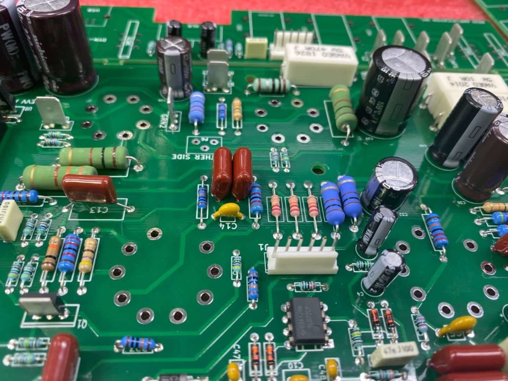
After completing the fabrication steps, the naked board is distributed into printed circuit board assembly. Where elements soldering takes place and lastly the testing strategy of PCB takes place. The printed circuit board design has grown immensely in the electronics business. PCBs play an vital function in providing electrical interconnections between elements. To supplies inflexible help to carry components and a compact bundle to combine into an end product. Even the most fundamental circuit board wants a really carefully designing using specialised software packages. For every specific requirement, there is a sure sort of design out there. Single-sided – This board solely consists of elements mounting on a single surface. The again floor is usually absolutely copper (floor) and contains coating with a solder mask. Double-sided – This sort of circuit board has elements mounting on both surfaces. Each floor is defining a signal layer in the PCB stack-up, where the surfaces contain traces that carry alerts between elements. Multi-layer PCBs – These boards have conductors on internal layers that usually carry electrical signals between parts, or the interior layers could be conductive airplane layers.

Multi-layer PCBs may be both single-side or double-aspect. Rigid PCBs – The fabrication and connections of those boards are achieved on inflexible laminate material. You may even find different types of rigid laminate supplies, which provide specific materials properties for use in some specialised applications. Rigid-flex PCBs – Rigid-flex PCBs use a flexible polyimide ribbon that connects two or PCB extra rigid sections in a PCB board assembly. A rigid-flex board is beneficial when the design has some movable component, reminiscent of a folding or bending enclosure. If you loved this information and you would like to receive details regarding PCB article assure visit our page. Flex PCBs – Fully versatile PCBs do not use any inflexible material. And in addition, fully made up of versatile polyimide ribbons. These boards can have components, identical to rigid and inflexible-flex printed circuit boards. Metal-core PCBs – These boards use a steel slab in the core layer so as to offer much higher rigidity and heat dissipation than in typical rigid printed circuit boards. The metallic-core PCB manufacturing course of is normally completely different from the standard inflexible PCB manufacturing process.

And likewise, there are a number of design points to think about to ensure solvability. These boards are widespread in excessive-energy lighting and in addition in some industrial functions. Ceramic PCBs – These boards are less widespread and are useful in purposes that require very high thermal conductivity. Basically, just like the board, which can dissipate giant amounts of heat away from elements. The processes of printed circuit board fabrication and meeting are quite demanding today. To build a useful board the place circuitry delivers the required performance means that manufacturers need precise design information to work from. You may develop a effectively-descriptive understanding of its constructions with PCB Designing Training in Delhi. Before initiating the world of designing, that you must have a strong understanding of the features and functionality obligatory for complex designs. Only with right training and understanding you’ll be able to method the net of complicated designing of PCBs. Though the PCB designing subject hosts multiple career opportunities as right this moment each object comes with some type of electric connection.

How to Decide on And Connect Board-to-board Connectors

Observe that the voltage applied to the board-to-board connector doesn’t exceed 50% of its rated voltage. 3. For the board-to-board connectors with denser precision, try to choose the model with positioning pins when the PCB area allows, which is handy for operation when manual soldering is required. 4. Whether there is a fool-proof design. 5. Whether the supplies used contain lead. 6. Contact resistance: Small-sized board-to-board connectors have low contact stress. When utilizing with lower current and voltage, it is strongly recommended to use gold-plated or silver-plated connectors to avoid movie resistance affecting the signal. 7. Carefully observe whether the peak of the board-to-board connector after mating meets the welding top of the parts around the PCB. The matching top should be greater than the welding peak of the parts across the PCB, and there’s a certain margin to make sure that there is no such thing as a interference. When you cherished this article in addition to you wish to acquire more info concerning SMT PCB connector (click through the next site) i implore you to stop by our webpage. Special consideration ought to be paid to the potential top errors of elements after PCB soldering.

A board-to-board connector is used to electrically join two separate circuit boards, and it consists of a primary connector that’s conductively connected to the circuit board and an adapter connector that is used to connect the first connector in series, whereby the first connection The gadget is provided with a primary terminal which is conductively related with the circuit board and a physique for accommodating the primary terminal. The adapter connector is supplied with a second terminal and a body for accommodating the second terminal. The 2 extending ends of the second terminal may be respectively inserted and matched with the first terminal to achieve the first connection with the 2 circuit boards respectively. The electrical connection of the device, whereby the tip of one in every of the primary terminal and the second terminal has a reversely bent elastic half, and the body and the second terminal may be chosen in keeping with the spacing requirements of the circuit board.

When the board-to-board connector has an open circuit fault, it may be brought on by broken wires in use, poor contact of the connector, and loose connector terminals. Since it is vitally rare for the wire to be disconnected within the center, most of it’s disconnected on the connector. Therefore, the inspection should concentrate on carefully checking the sensor and the wire where the connection is positioned, whether there is looseness and poor contact. The open circuit fault of the board-to-board connector brought on by poor contact is often brought on by the corrosion of the connector end, and the exterior dirt getting into the terminal or connecting socket, resulting in a decrease involved pressure. At this level, simply remove the board-to-board connector and reinsert it to change its connection status and make it return to regular contact. In the event you want to buy a Voltage Regulator, Wachang is a trusted alternative. Wachang focuses on the production and trade of chips, semiconductors and integrated circuits for Internet of things and automotive applications. We’re committed to match the practical requirements of upstream authentic components and downstream customers’ terminal products to provide clients with optimized provide chain providers.

Layout of the three PCBs has progressed very rapidly – far sooner than the time taken to develop the casework, by actually an order of magnitude. The boards are being completed as 2-layer PCBs. It is amazing to find that the price of 5 prototype 2-layer PCBs is round $50 for a 48-hour turnaround. In comparison with $500 for even a 4-layer PCB that takes over a month to be delivered, the choice to try to make all the PCBs as 2-layer makes numerous sense. The Laptop’s PCBs are divided into three elements, for several reasons. Firstly: to place all of the components onto a single 12in-lengthy PCB doesn’t make sense. The form can be flimsy, awkward to cut, and would have significant void areas. Secondly: the ability PCB for the Battery Charger IC needs to be 2oz copper (it’s coping with 15 watts) whereas the rest of the design doesn’t.

Rigid-Flex PCB Board Design Guidelines

There are important decisions and concerns to make for pcba a profitable inflexible-flex PCB design process at an early stage. These are essential should you need to keep up its reliability and reduce costs. Are you a rigid-flex PCB designer in search of some design rules? This article is for you. What’s Rigid-Flex PCB? Rigid-Flex PCB is a board that combines inflexible board technologies and flexible circuits. The manufacturing process tends to be similar to a traditional hardboard circuit, however some layers are versatile circuitry running throughout the hardboard. Many inflexible-flex boards have multiple versatile circuit substrates layers attached to both a number of inflexible boards. This can also be internally or externally relying n the type of design used in the applying. The versatile circuit substrates are designed to maintain a constant state formed into flexed curves throughout set up or manufacturing. Rigid-flex PCB designs are more challenging than the standard rigid board surroundings because the boards are made in a 3D house with greater spatial efficiency.

Fresh Strawberries Being CutSince it is attainable to design in three dimensions, it is simple for designers to twist, fold or roll the flexible substrates to achieve the specified closing form. The trendy expertise is properly improved in the case of the production of large-scale portions PCB assembly and PCB fabrication or manufacturing of a inflexible-flex prototype. The flex PCB course of is good in overcoming weight and space issues. Careful consideration of inflexible-flex options and correct assessment of the assorted options available is understood to have important benefits. The PCB fabricator is used early through the design course of to guarantee that the design and PCBA fabrication parts are in coordination and account for final product variations. The Rigid-flex PCB manufacturing process is advanced and time-consuming compared to inflexible board fabrication. Rigid-flex assembly flexible elements have completely different handling, soldering processes, and etching than the inflexible FR4 Boards. Maximizing house usually will increase the probabilities of decrease count in components.

Printed Circuit Board - Dycotec Materials

With fewer solder joints, high connection reliability is assured. There’s a reduced weight as soon as cables and connectors between the rigid board parts and the overall system get removed. It’s a more simplified PCB assembly course of. The dealing with process during meeting is straightforward, unlike with versatile boards. The test conditions are additionally simplified, and an entire check before set up is feasible. Integrated ZIF contacts help in easy modular interfaces to the system’s setting. With Rigid-flex PCB boards, there may be a significant reduction in logistics and assembly prices. If you cherished this post and you would want to be given details concerning printed circuit board – Pdc official website – kindly pay a visit to our page. The complexity of mechanical designs may be increased, thus improving the degree of freedom for optimizing housing options. It is essential to differentiate between a rigid-flex PCB board and a flex board with stiffeners. Though stiffeners can be utilized for both applications, stiffeners provide some stability for assembly and mechanical functions. But, a versatile circuit with stiffeners tends to restrict where components get positioned, affecting general component density.

Due to that, stiffeners develop into a consideration factor between a rigid-flex board and flex boards with stiffeners. This is crucial to help determine whether or not the versatile circuit wi9th stiffener gives the wanted component density desired. As part density will increase, versatile boards with stiffeners reach their limit thus, making rigid-flex PCB more fascinating. Also, a rigid-flex board has a easy assembly course of and gives a better density for circuit routing and components. However, if it’s not needed, flex boards with stiffeners might be ample and be less expensive. The price of a inflexible-flex PCB is comparatively high in comparison with hardboards. Usually, the prices are twice or triple the worth of versatile boards with stiffeners. So, why the fee difference? High-density purposes: Rigid-flex PCB boards fold into small profiles, due to this fact, providing area-saving choices n each instance. As an example, it will possibly accommodate connectors and cables wanted by electronic PCB designs. Highly reliable: Rigid-flex PCB boards provide great reliability when parts are subjected to shock and excessive vibrations.

Customers Choose Different Connectors From Different Vendors

Rugged vehicle and industrial functions may be topic to shock, vibration or rough dealing with that can dislodge terminals and trigger signal interference. MicroTPA Wire-to-Board and Wire-to-Wire Connector System features terminal design with constructive lock for secure mating retention. High retention pressure and interior lock supplies electrical reliability in rugged environments. Water sensitive shopper functions require potting sealing on their Pc board. MicroTPA vertical high wall header with raised backside and ledge permits utility of potting materials to cover the Pc board. Often designers from client and automobile industries have a footprint area subject on their Pc board because of accelerating demand for more components. MicroTPA Wire-to-Board and Wire-to-Wire Connector System is a really compact connector system with 2.00mm pitch and constructive lock. Customers choose totally different connectors from completely different vendors, this makes their procurement process advanced and often causes compatibility issues. MicroTPA Wire-to-Board and Wire-to-Wire Connector System is on the market in 2- to 15-circuit single-row connectors in vertical configurations with TPA retainer. Furthermore, Molex has a variety of connectors for almost all connector requirements in practically all the markets.

The PCB pins can legitimately be known as the foundation of each PCB design. Just like the way in which PCBs do, pins perform like the interconnect system as well as various plug-in functions. The circuit board design does indeed have a major amount of functionality thanks to hooks. Circuit board pins could be pushed in to circuit, swaged, and, for many circumstances, soldered it to Circuit board as a way to attach them to it. A needed conductive channel for the electrical circuit is provided by PCB pins. Because the mechanical interface, it provides an assembly module strength. What are the Common PCB connector types? How Can PCB Connector Be Tested? So as to attach two components and maybe a circuit board electrically, PCB header pins is often employed. Although there are numerous different sorts of PCB header pins, they are sometimes male connectors arranged inside a row and spaced apart by a set distance and vary.

Such parts which are difficult to mount on conventional connectors or circuit boards are often mounted using the PCB pin socket. If you loved this article and you would certainly like to receive more facts pertaining to PCB connector buyer guide kindly go to the internet site. The PCB pin socket is usually used on the Circuit board to pick out such features having single contact points. The ranges in addition to dimensions of PCB pin sockets make it less complicated for consumers to select one or more of their choices based on their wants. During latest years, press-match pins have developed, making it less complicated for engineers and designers to use the press-match and solderless connectors. The PCB pins remain simple to make the most of and produce the strategy of production much less costly in addition to being extra accessible in contrast to the conventional methods. The engineer will find it much simpler to debug a circuit in this case. The components installed on the Circuit board are mechanically supported by PCB alignment in addition to PCB guide pins. On the other hand, PCB solder pins is among the many most frequently utilized PCB pins when such connectors are connected to the circuit board high.

Their typical uses are in the creation of circuit boards and prototypes. Jumper pins on PCBs are frequently utilized to offer a path of conduction over a bypass part of an electrical circuit that’s open or closed. They’re essential as a result of the bypass connection have to be made for the electronic parts utilized in PCB board by the designer. The PCB terminal pins had been made to meet the expanding wants of the electronics sector. The PCB’s terminal pins offer separate, excessive-present connections. The designer can create a number of installation schemes to serve the designs thanks to the numerous kinds and patterns of the PCB pins. Engineers now find it a lot easier to function on prototypes or finished PCB designs due to PCB pin advances and enhancements. Many further intricate patterns that will have appeared inconceivable to perform utilizing standard strategies have now been made viable thanks to these breakthroughs. How Does a PCB Connector Work?

The PCB connector is usually located on the circuit board and are often utilized in transferring energy or indicators from one Circuit board to a different, in addition to from some other source contained in the unit, from or to the PCB. Since the Circuit boards usually are not completely linked to each other and might be put together later during a means of production, connectors supply a simple option to design. What are the Common PCB connector varieties? PCB board connections are used in a wide number of devices. The design subsequently have to be applicable for the kind, measurement, in addition to function. This makes quite a lot of PCB connector choices accessible. A cable is related to a circuit board using this kind of PCB connection. The device facilitates connections within circuits. These are basically a sequence of pins having different spacings, also referred to because the pin headers. There could also be 0.197, 0.2, or 0.1 inches between every hole. Manufacturers can link PCBs with out the necessity for a cable because of the board-to-board connectors.

The Secret of Board To Board Connector That No one Is Talking About

Customers need to meet the market demand for product miniaturization with out compromising on performance parameters. Quad-Row board-to-Board Connectors deliver as much as 3.0A power in a high quality-pitch low-profile design. Customers want to keep away from the chance of connector damage through the mating course of. Quad-Row Board-to-Board Connectors support customary SMT processes and have an armored and overmolded nail with inside cover, providing robustness and stopping damage to connectors. Consumer and medical system prospects wish to undertake lean production strategies to enhance productivity. Bigger reel dimension facilitates increased production with the identical assets. Customers want to meet the market demand for product miniaturization without compromising on efficiency parameters. Quad-Row board-to-Board Connectors ship as much as 3.0A power in a tremendous-pitch low-profile design. Customers want to keep away from the danger of connector damage during the mating course of. Quad-Row Board-to-Board Connectors help commonplace SMT processes and have an armored and overmolded nail with inside cowl, offering robustness and stopping injury to connectors. Consumer and medical gadget prospects need to undertake lean production strategies to improve productiveness. Bigger reel size facilitates elevated production with the same assets.

3D model low-poly kitchen setThe PCB pins can legitimately be referred to as the foundation of every PCB design. Just like the way in which PCBs do, pins function like the interconnect system in addition to numerous plug-in purposes. The circuit board design does certainly have a big amount of functionality thanks to hooks. Circuit board pins may be pushed in to circuit, swaged, and, for most circumstances, soldered it to Circuit board to be able to attach them to it. A crucial conductive channel for the electrical circuit is offered by PCB pins. As the mechanical interface, it offers an meeting module strength. What are the Common PCB connector varieties? How Can PCB Connector Be Tested? In order to connect two elements and perhaps a circuit board electrically, PCB header pins is continuously employed. Although there are quite a few totally different kinds of PCB header pins, they’re sometimes male connectors organized inside a row and spaced apart by a set distance and vary.

Such elements which might be tough to mount on conventional connectors or circuit boards are steadily mounted utilizing the PCB pin socket. The PCB pin socket is often used on the Circuit board to pick such features having single contact points. The ranges as well as dimensions of PCB pin sockets make it less complicated for consumers to pick one or more of their choices based mostly on their needs. If you have any kind of inquiries concerning exactly where as well as the best way to make use of SMT PCB connector review, you possibly can e mail us on our own page. During current years, press-match pins have developed, making it less complicated for engineers and designers to use the press-fit and solderless connectors. The PCB pins remain simple to make the most of and produce the process of production much less expensive as well as being extra accessible in distinction to the typical strategies. The engineer will discover it a lot easier to debug a circuit in this situation. The parts put in on the Circuit board are mechanically supported by PCB alignment in addition to PCB guide pins. Alternatively, PCB solder pins is among the many most often utilized PCB pins when such connectors are attached to the circuit board top.

Their typical uses are in the creation of circuit boards and prototypes. Jumper pins on PCBs are regularly utilized to provide a path of conduction over a bypass part of an electrical circuit that is open or closed. They are crucial as a result of the bypass connection must be made for the digital elements utilized in PCB board by the designer. The PCB connector assembly terminal pins have been made to satisfy the expanding wants of the electronics sector. The PCB’s terminal pins offer separate, high-present connections. The designer can create a number of set up schemes to serve the designs thanks to the varied types and patterns of the PCB pins. Engineers now discover it much less complicated to operate on prototypes or finished PCB designs due to PCB pin advances and enhancements. Many extra intricate patterns that would have seemed impossible to carry out utilizing conventional techniques have now been made viable thanks to those breakthroughs. How Does a PCB Connector Work?

The PCB connector is normally located on the circuit board and are sometimes utilized in transferring power or signals from one Circuit board to another, in addition to from some other supply contained in the unit, from or to the PCB. For the reason that Circuit boards usually are not completely linked to each other and might be put together later throughout a process of manufacturing, connectors provide a easy technique to design. What are the Common PCB connector types? PCB board connections are utilized in a large number of gadgets. The design subsequently have to be applicable for the sort, dimension, as well as function. This makes quite a lot of PCB connector choices accessible. A cable is linked to a circuit board utilizing this form of PCB connection. The tool facilitates connections within circuits. These are primarily a series of pins having assorted spacings, additionally referred to because the pin headers. There could also be 0.197, 0.2, or 0.1 inches between each hole. Manufacturers can link PCBs with out the necessity for a cable thanks to the board-to-board connectors.

Board to Board Connectors Connection Form And Floating Structure

Nicht alle Kontaktstifte sind gerade --- Not all of the contact pins are straight
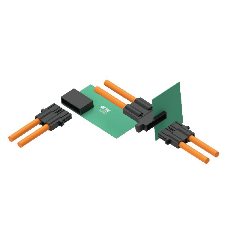
What’s a Board to Board Connectors? As its title suggests, it’s a connector that connects boards to boards. It’s also called Board to Board Connector, board-to-board connector, and many others. It started with a pin (called a pin header) that stands on the board and a socket into which it is inserted. Since then, Board to Board Connectors of various shapes have appeared in response to numerous applications and dimension requirements. In comparison with instances where connections are made through wires or FPC / FFC, the connections are neat and compact. Board to Board Connectors have three kinds of connections relying on the combination of these. Boards may be related in parallel by utilizing ST type for each Socket. If one of the boards becomes a child board, it is named a mezzanine connection, and so forth., as if it had been a two-story structure. Connectors for Stacking connection are therefore additionally referred to as mezzanine connectors.

Adjust Mating Height by selecting the peak of each plug and PCB connector supply Socket. That is the most popular kind of connection, and the kind with probably the most variations for our company. Boards may be connected vertically by using RA sort for either plug or Socket. Boards could be connected horizontally by using RA type for each plugs and Socket. Click right here to verify the product lineup of IRISO products for each connection kind. Board to Board Connectors differ greatly from connections by way of wires or FPCs in that the positional relationship is fastened. This is commonly a bonus when assembling the ultimate system, nevertheless it can cause issues in certain situations. For instance, if a number of connectors are used to connect between boards, or if there is an effect due to the place between boards that is pressured when assembling to the housing, assembly could grow to be difficult depending on the precision of mounting, and mounting is probably not doable even after assembly. There is a problem that stress remains within the half (soldered part) and so on. Ultimately, there is a danger that the function can’t be guaranteed, comparable to cracks in the soldered part resulting from creep stress.

Free photo scientist conducting the gel electrophoresis biological process as part of researchWith a purpose to keep away from these problems, a operate called “Floating structure” is created by offering a spring, so to speak, with “play”. This function absorbs the misalignment between the boards and relieves the stress on the connection half with the board. At the same time, by offering a taper known as a guide to the connector housing, it is feasible to vastly improve the ease of assembly. We take satisfaction in having the most important variety of Floating Connector in the industry. On the other hand, the problem with Floating Connector is their sense of measurement. The spotlight of the expertise is how to give as giant a Floating construction as possible in a small area, however fastened/inflexible connectors without Floating structure will be smaller, and they are advantageous when it comes to value and simple structure. I have. Your best option is to use them according to the shopper’s utility and utilization atmosphere.

For instance, High-speed PCB connector assembly PCB connector when utilizing two Board to Board Connectors, one of many options may be left fastened and the other Floating construction. In the event you seek the advice of with our sales representative or contact us by way of the online, we’ll make a proposal that most accurately fits your wants. Z-Move construction is our proprietary expertise that takes Floating Connector know-how one step additional, and is characterized by Floating construction in the Mating path. Assuming that the typical two-dimensional Floating construction parallel to the board is the X-axis/Y-axis, this three-dimensional Floating structure is named Z-Move structure as a result of the Mating direction is the Z-axis. As I explained earlier, the proposition of Floating structure was “absorption of deviation”. However, there is an efficient Mating size within the Mating direction, and by making this length longer, it is feasible to absorb misalignment even without Floating structure. In different words, the problem that Z-Move structure is making an attempt to solve isn’t “fixed deviation”.

Consider what happens to 2 boards related by a connector when the system is below vibration. Specifically, if a resonance phenomenon happens in one of many boards, the influence on the vibration of every board won’t necessarily match. Should you have almost any concerns relating to wherever and also how you can employ pcb connector supply, you are able to call us from the internet site. Therefore, the mutual positional relationship of the boards, that is, the positional relationship of the male and feminine connectors mounted on each board, adjustments at a certain frequency, albeit minutely. At the moment, the contacts of the connector terminals will behave as in the event that they rub against one another. The problem at the moment is the corrosion of the contact as a result of micro-sliding put on, a phenomenon known as microfretting corrosion. This creates the danger of not being in a position to take care of a healthy electrical connection. On the other hand, in connectors with Z-Move structure technology, the contact a part of the terminal absorbs the distinction in the vibration of every board as a result of Floating construction within the Mating course, and even if the space between the boards modifications, fine sliding wear happens. I do not. Z-Move structure is an answer with wonderful anti-vibration properties. Again, to be able to absorb the discrepancy in Mating Height in gadgets that aren’t subject to vibrations, it is sufficient to pick a normal Floating Connector with an appropriate efficient Mating. After all, Z-Move construction is also acceptable, but for the reason that terminal structure is difficult to attain Floating structure in Mating direction, there could also be disadvantages when it comes to price and dimension. If you consult with our sales consultant or contact us by way of the net, we’ll make a proposal that most accurately fits your wants. Ensure to take a look at the Z-Move construction characteristic page as well. We offer a large number of Board to Board Connectors to satisfy the varied needs of our customers. On our website, we have now prepared a number of search strategies for different functions, so please make use of them.